THERMAL ENGINEERING-1 (UNIT-2)
UNIT-2
I. C. ENGINES : Classification - Working principles, Valve and Port Timing Diagrams, - Engine systems –Fuel, Carburettor, Fuel Injection System, Ignition, Cooling and Lubrication, principle of wankel engine,principles of supercharging and turbo charging.
I.C Engines Classification:


Port Timing Diagram:


Four Stroke Engine - Working:
Four stroke engine consists of 4 strokes with two complete revolutions of crank.
Suction Stroke:

Compression Stroke:

Expansion / Power Stroke:

Exhaust Stroke:

Valve Timing Diagram:


COMPARISON BETWEEN TWO STROKE AND FOUR STROKE ENGINES


I.C Engines Classification:
- According to combustion:Internal combustion (I.C) and External Combustion (EC)
- According to Type of fuel used: Petrol, diesel , gas / Alternative Fuels
- According to Number of strokes –Two stroke , four stroke
- According to Type of ignition such as Spark Ignition (SI), Compression Ignition (CI)
- According to Number of Cylinders – From 1 to up to 18 cylinders (in a car)
- According to Arrangement of cylinders which are Inline, V, W, Horizontal, Radial
- According to Motion of Pistons which are Reciprocation, Rotary
- According to Size / Capacity
- According to Bore-to-Stroke Ratio
- According to Engine cooling methods such as Air-cooled, Liquid-cooled (Water based), Oil-cooled (Oil is cooled separately)
- According to Breathing such as Naturally Aspirated, Turbocharged / Supercharged
- According to Applications such as Bikes, Passenger Cars, Racing cars, Commercial Vehicles, Marine, Agricultural equipment and Earth-moving equipment etc.
Two Stroke Engine - Working:
The two stroke engine employs both the crankcase and the cylinder to achieve all the elements of the Otto cycle in only two strokes of the piston.
Intake: The fuel/air mixture is first drawn into the crankcase by the vacuum that is created during the upward stroke of the piston. The illustrated engine features a poppet intake valve; however, many engines use a rotary value incorporated into the crankshaft.

Crankcase compression: During the downward stroke, the poppet valve is forced closed by the increased crankcase pressure. The fuel mixture is then compressed in the crankcase during the remainder of the stroke.
Transfer/Exhaust: Toward the end of the stroke, the piston exposes the intake port, allowing the compressed fuel/air mixture in the crankcase to escape around the piston into the main cylinder. This expels the exhaust gasses out the exhaust port, usually located on the opposite side of the cylinder. Unfortunately, some of the fresh fuel mixture is usually expelled as well
Compression:The piston then rises, driven by flywheel momentum, and compresses the fuel mixture. (At the same time, another intake stroke is happening beneath the piston).
Power: At the top of the stroke, the spark plug ignites the fuel mixture. The burning fuel expands, driving the piston downward, to complete the cycle. (At the same time, another crankcase compression stroke is happening beneath the piston.)

Since the two stroke engine fires on every revolution of the crankshaft, a two stroke engine is usually more powerful than a four stroke engine of equivalent size. This, coupled with their lighter, simpler construction, makes the two stroke engine popular in chainsaws, line trimmers, outboard motors, snowmobiles, jet-skis, light motorcycles, and model airplanes.
Unfortunately, most two stroke engines are inefficient and are terrible polluters due to the amount of unspent fuel that escapes through the exhaust port.
Four Stroke Engine - Working:
Four stroke engine consists of 4 strokes with two complete revolutions of crank.
The strokes are named as
1.Suction stroke
2.Compression stroke
3.Expansion / Power stroke
4.Exhaust stroke
Suction Stroke:
Suction stroke occurs when piston moves from TDC to BDC. In this stroke inlet valve opens and fresh charge (air and fuel in case of SI engine , only air in case of CI engine) enters in to engine chamber. The outlet / exhaust valve remains close.
Compression Stroke:
After the suction stroke ends the pistons moves from BDC to TDC again to compress the fresh charge. Due to compression fresh charge temperature and pressure will increase. In compression stroke both inlet and outlet valves are in close position
At the end of the compression stroke the fresh charge is just sufficient to combustion process. Here a spark is initiated with the help of spark plug (in case of SI engines) / fuel is injected with the help of fuel injectors (in case of CI engines). Then combustion takes place which results to release high energy. Due to this the piston moves downwards from TDC to BDC with both valves closing position.
After the power stroke the piston travels from BDC to TDC again. Because of the fuel combustion process gases like CO2,H2,N2 forms. The burnt gases will be kicked out by exhaust stroke by the opening of exhaust valve.
DIAGRAM NOTATION:
I.V - INLET VALVE
E.V - EXHAUST VALVE
C - CRANK
C.R - CONNECTING ROD
E.C - ENGINE CYLINDER
S.P - SPARK PLUG
Valve Timing Diagram:
COMPARISON BETWEEN TWO STROKE AND FOUR STROKE ENGINES
COMPARISON OF DIESEL ENGINE WITH PETROL ENGINE
Engine systems:
1. Fuel supply system
2. Lubrication system
3. Ignition system
4. Cooling & Lubrication system
5. Governor
Fuel is a substance consumed by the engine to produce power. The common fuel for
Internal Combustion engines are
1. Petrol
2. Power kerosene
3. High speed diesel
FUEL SUPPLY SYSTEM IN SPARK IGNITION ENGINE
The fuel supply system of spark ignition engine consists of
1. Fuel tank
2. Sediment bowl
3. Fuel lift pump
4. Carburetor
5. Fuel pipes
FUEL SUPPLY SYSTEM IN DIESEL ENGINE
Fuel supply system of diesel engine consists of the following components
1. Fuel tank
2. Fuel lift pump or fuel feed pump
3. Fuel filter
4. Fuel injection pump
5. High pressure pipe
6. Over flow valve
7. Fuel injector
Carburetor:
The process of preparing air-fuel mixture away from the engine cylinder is called
carburetion and the device in which this process takes is called carburetor.
Functions of carburetor
1. To mix the air and fuel thoroughly
2. To atomize the fuel
3. To regulate the air- fuel ratio at different speeds and loads on the engine.
4. To supply correct amount of mixture at different speeds and loads
Carburetor Working Principle:

Carburetor Working Principle:
1. Float Chamber:
The float chamber serves as a storage tank of fuel for continuous supply of fuel. It contains a float valve which maintains the level of fuel in float chamber. When the level of fuel decreases in float chamber the float moves downward, which open the fuel supply valve and allow flow of fuel into float chamber. As the fuel level increases, the float moves upward which close and stop the fuel supply. This fuel level is maintained below the discharge nozzle outlet hole to prevent overflow.
2. Strainer:
It is a device which is used to filter the fuel before entering into float chamber. It consist a fine wire mesh which filters the fuel and removes dust and other suspended particles from it. These particles if not removed can cause blockage of nozzle.
3. Metering System:
The metering system controls the flow of fuel into nozzle. It is responsible to form correct mixture of air fuel. It consist two main parts, first one is known as metering orifice and other one is known as fuel discharge nozzle.When the air passes through venturi, it generates a low pressure field across throat compare to pressure at float chamber. Due to this pressure difference, fuel is discharge into the air stream. The quantity of fuel is control by the metering orifice and discharge hole at the exit of fuel discharge nozzle.
4.Idling system:
4.Idling system:
It consist a passage directly from the float chamber to venturi tube. It provides rich mixture during idling and at low speed. It works during idling or when the throttle is open below 15%.
5.Throttle Valve:
It is a butterfly valve situated at the exit of the venturi tube. It controls the speed of the vehicle by providing control amount of mixture. It controls the quantity of air fuel mixture. If throttle is fully opened, than more mixture drawn into cylinder and thus gives high output. But if it is little opened, less mixture is drawn into the cylinder, which gives less power.
6.Choke Valve:
It is same as throttle valve in construction but situated at the entrance of venturi tube. It is used to provide very rich mixture during starting in cold season. It controls the quantity of air flow through the venturi tube. If the choke is fully open, normal amount of air flow through venturi, which forms a normal mixture. But if the choke is partially closed, it results low amount of air flow through venturi and large amount of fuel flow through discharge nozzle. It gives rich mixture.
Working:

Working:
- First fuel is supplied into the float chamber through strainer. Strainer works as a filter. It does not allow dust and other suspended particles into the float chamber which can choke any fuel passage.
- The float maintains a constant level of fuel into float chamber. If the amount of fuel in the float chamber goes down below designed limit, the float goes down which opens the fuel supply valve and allow fuel to flow into float chamber. If the fuel reaches designed limit, the float goes up, which closes the fuel supply valve and thus stop fuel supply into float chamber.
- The fuel discharge nozzle connects float chamber to venturi tube. The one end of fuel supply nozzle connected to the bottom of the float chamber and other one is to the venturi tube slightly above the designed fuel level in the float chamber. This will avoid overflow when engine is not running.
- During suction stroke air is drawn into cylinder through venturi tube. Venturi is a tube of decreasing cross section and has a minimum area at throat. The fuel supply nozzle connects at the throat of venturi tube. This air has maximum velocity at throat. Due to this high velocity, the pressure at the throat goes down below float chamber pressure.
- This will create a pressure difference between float chamber and venturi tube. This pressure difference is known as carburetor depression. It acts as driving force for fuel. It drives fuel from float chamber to venturi tube through fuel supply tube and the fuel is discharged into the air stream.
- The fuel-air ratio depends on the size of discharge jet and metering system. So they are chosen as such, they can give desired air-fuel ratio.
- This air fuel mixture provided to the cylinder through throttle valve. The SI engine is a quantity governed engine. So the quantity of the mixture provided into the cylinder is controlled by the throttle valve and hence control output power.
- For idling or when required rich mixture, extra fuel is supplied by the idling system into venturi tube.
Fuel Injection System:
- A fuel injector is an electronically controlled mechanical device which is used to inject/spray (just like a syringe) the fuel into the engine for the preparation of correct air-fuel mixture which in turn provides efficient combustion to the engine
- The position of the fuel injectors differs for different engine designs but usually they are mounted on the engine head with a tip inside the combustion chamber of the engine
- In case of carburetors, controlling the air-fuel mixture quality and timing(fuel metering) is not precised as in carburetors, the adjustments can be done mechanically, but when it comes to fuel injectors due to its smart electronically controlled unit or e.c.u high precision of fuel metering can be achieved.
- It has been seen that not only the mileage but also the performance of the fuel injected vehicles is better than that of carbureted vehicles.
The injector is an electro-mechanical device, which is fed by a 12 volt supply
from the ECM.
The injector consists of a solenoid operated valve which is held in the closed
position by a spring until the earth circuit is completed by the ECM. When the
electromagnetic field lifts the needle off its seat, fuel is delivered to the
engine. The total lift on the needle is approximately 0.15 mm and has a
reaction time around 1 millisecond.
Ignition System:
Basically Convectional Ignition systems are of 2 types :
(a) Battery or Coil Ignition System, and
(b) Magneto Ignition System.
(a) Battery or Coil Ignition System:
Figure shows line diagram of battery ignition system for a 4-cylinder petrol engine. It mainly consists of a 6 or 12 volt battery, ammeter, ignition switch, auto-transformer (step up transformer), contact breaker, capacitor, distributor rotor, distributor contact points, spark plugs, etc. Note that the Figure 4.1 shows the ignition system for 4-cylinder petrol engine, here there are 4-spark plugs and contact breaker cam has 4-corners. (If it is for 6-cylinder engine it will have 6-spark plugs and contact breaker cam will be a perfect hexagon).
The ignition system is divided into 2-circuits :
(i) Primary Circuit : It consists of 6 or 12 V battery, ammeter, ignition switch, primary winding it has 200-300 turns of 20 SWG (Sharps Wire Gauge) gauge wire, contact breaker, capacitor.
(ii) Secondary Circuit : It consists of secondary winding. Secondary Ignition Systems winding consists of about 21000 turns of 40 (S WG) gauge wire. Bottom end of which is connected to bottom end of primary and top end of secondary winding is connected to centre of distributor rotor. Distributor rotors rotate and make contacts with contact points and are connected to spark plugs which are fitted in cylinder heads (engine earth).
Working : When the ignition switch is closed and engine in cranked,
as soon as the contact breaker closes, a low voltage current will flow
through the primary winding. It is also to be noted that the contact
beaker cam opens and closes the circuit 4-times (for 4 cylinders) in
one revolution. When the contact breaker opens the contact, the
magnetic field begins to collapse. Because of this collapsing magnetic
field, current will be induced in the secondary winding. And because
of more turns (@ 21000 turns) of secondary, voltage goes unto
28000-30000 volts. This high voltage current is brought to centre of the distributor rotor. Distributor
rotor rotates and supplies this high voltage current to proper stark plug depending
upon the engine firing order. When the high voltage current jumps the spark plug
gap, it produces the spark and the charge is ignited-combustion starts-products of combustion expand and produce power.
(b) Magneto Ignition System:
In this case magneto will produce and supply the required current to the primary winding. In this case as shown, we can have rotating magneto with fixed coil or rotating coil with fixed magneto for producing and supplying current to primary, remaining arrangement is same as that of a battery ignition system.
Engine cooling:
There are mainly two types of cooling systems :
(a) Air cooled system, and
(b) Water cooled system.
Air Cooled System
Air cooled system is generally used in small engines say up to 15-20 kW and in
aero plane engines.
In this system fins or extended surfaces are provided on the cylinder walls,
cylinder head, etc. Heat generated due to combustion in the engine cylinder will be
conducted to the fins and when the air flows over the fins, heat will be dissipated
to air.
The amount of heat dissipated to air depends upon :
(a) Amount of air flowing through the fins.
(b) Fin surface area.
(c) Thermal conductivity of metal used for fins.
Advantages of Air Cooled System
Following are the advantages of air cooled system :
(a) Radiator/pump is absent hence the system is light.
(b) In case of water cooling system there are leakages, but in this case
there are no leakages.
(c) Coolant and antifreeze solutions are not required.
(d) This system can be used in cold climates, where if water is used it
may freeze.
Disadvantages of Air Cooled System
(a) Comparatively it is less efficient.
(b) It is used only in aero planes and motorcycle engines where the engines are
exposed to air directly.
Air Cooled System
There are two types of water cooling system :
Thermo Siphon System
In this system the circulation of water is due to difference in temperature
(i.e. difference in densities) of water. So in this system pump is not required
but water is circulated because of density difference only.
Pump Circulation System
In this system circulation of water is obtained by a pump. This pump is
driven by means of engine output shaft through V-belts.
Engine Lubrication:
- An automobile engine, engine oil/lubricating oil is used to reduce friction between pistons and cylinders so that pistons may slide up and down in the cylinders smoothly thereby avoiding wastage of fuel energy in overcoming friction.
- Lubricating oil reduces wear and tear in sliding/moving parts of machines thereby prolonging their life.
Splash Lubrication System:
The splash system is no longer used in automotive engines. It is widely used in small four-cycle engines for lawn mowers, outboard marine operation, and so on. In the splash lubricating system (fig.), oil is splashed up from the oil pan or oil trays in the lower part of the crankcase. The oil is thrown upward as droplets or fine mist and provides adequate lubrication to valve mechanisms, piston pins, cylinder walls, and piston rings. In the engine, dippers on the connecting-rod bearing caps enter the oil pan with each crankshaft revolution to produce the oil splash. A passage is drilled in each connecting rod from the dipper to the bearing to ensure lubrication. This system is too uncertain for automotive applications. One reason is that the level of oil in the crankcase will vary greatly the amount of lubrication received by the engine. A high level results in excess lubrication and oil consumption and a slightly low level results in inadequate lubrication and failure of the engine.
Advantages:
- Very cheap in cost
- Easy in construction
Disadvantages:
- This is not a positive lubrication system i.e we can not send the oil in to the deserve positions
Pressure Lubrication System:
In pressurized lubrication system, the lubricating oil is supplied by a pump under pressure to all parts requiring lubrication as shown in below figure. The oil under the pressure is supplied to main bearings of the crank shaft and camshaft. Holes drilled through the main crank shaft bearings journals, communicate oil to big end bearing and small end bearings through the hole drilled in the connecting rod. a pressure gauge is provided to confirm the circulation of oil to various parts.This system provides sufficient lubrication to all parts and is favored by most of the engine manufacturers. This is used in most heavy duty and high-speed engines.
Wankel Engine:
Rotor :The rotor has three convex faces which acts like a piston. The 3 corners of rotor forms a seal to the outside of the combustion chamber. It also has internal gear teeth in the centre on one side. This allows the rotor to revolve around a fix shaft
.
Housing :The housing is epitrochoidal in shape(roughly oval). The housing is cleverly designed as the 3 tips or corners of the rotor always stay in contact with the housing. The intake and exhaust ports are located in the housing.
Inlet & exhaust ports :The intake port lets fresh mixture enter into combustion chamber & the exhaust gases expel out through outlet/exhaust port.
Spark plug :A spark plug delivers electric current to the combustion chamber which ignites the air-fuel mixture leading to abrupt expansion of gas.
Output shaft :The output shaft has eccentric lobes mounted on it, which means they are offset from centreline of the shaft. The rotor is not in pure rotation, but we need these eccentric lobes for pure rotation of the shaft.
Working

Working
Intake :
When a tip of the rotor passes the intake port, fresh mixture starts entering into the first chamber. The chamber draws fresh air until the second apex reaches the intake port & closes it. At the moment, fresh air-fuel mixture is sealed into first chamber & is being taken away for combustion.
Compression :
The chamber one(between corner 1 to corner 2) containing the fresh charge gets compressed due to shape of the engine by the time it reaches to spark plug.
While this happens, a new mixture starts entering into the second chamber(between corner 2 to corner 3).
Combustion:
When the spark plug ignites, the highly compressed mixture expands explosively. The pressure of expansion pushes the rotor in forward direction. This happens until the first corner passes through the exhaust port.
Exhaust:
As the peak OR corner 1 passes exhaust port, the hot high pressure combustion gases are free to flow out of the port. As the rotor continues to move, the volume of chamber goes on decreasing forcing the remaining gases out of port. By the time the corner 2 closes the exhaust port, corner 1 passes by the intake port repeating the cycle. While the first chamber is discharging gases, the second chamber(between corner 2 to corner 3) is under compression.Simultaneously, chamber 3(between corner 3 to corner 1) is drawing fresh mixture
Advantages :
- Wankel engine has a very few moving parts; far less than 4 stroke piston engine. This makes the design of the engine simpler & the engine reliable.
- It is approximately 1/3rd of the size of the piston engines delivering same power output.
- Able to reach higher revolutions per minute than a piston engine.
- Wankel engine weighs almost 1/3rd of the weight of the piston engines delivering same power output. This leads to a higher power to weight ratio.
Disadvantages:
- As each section has temperature differences, the material expansion of housing is different at different region. Therefore, the rotor is unable to completely seal the chamber in high temperature region sometimes.
- The combustion is slow as the combustion chamber is long, thin, and moving. Hence, there might be a possibility that the fresh charge discharges out without even burning.
- As unburnt fuel is in the exhaust stream, emissions requirements are difficult to meet.
Supercharging:
Supercharging is the process of introducing air in to an engine inlet above the atmospheric pressure by means of using a compressor. Generally the compressor is known as Supercharger / Pressure booster.
- The fresh air enters in to compressor where it is to be compressed above the atmospheric pressure (P1) , the final pressure of compressed air (P2) is surely high.
- The pressurized air is send in to engine inlet valve there after combustion chamber in order to increase the efficiency of the engine.
- The compressor draws the running power from engine crankshaft with the help of belt drive.
Advantages:
- Cheaper than turbo charger
- Increases engine output
- Regulate the pollution emissions
- Quick acceleration of vehicle
- Vehicles cost increases compared to with out supercharged vehicle
- Engine design must be strong to resist extra pressure effects
- Supercharger consumes the running power from engine
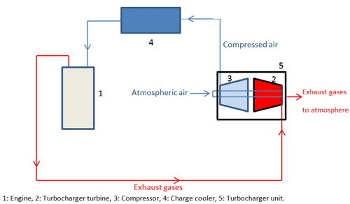
Turbo charging:
Turbo charging is the process as similar to super charging ,but here the compressor is to be run with the exhaust gases energy by means of using a turbine. The device which consists of both compressor and turbine is known as turbo charger has to use here. The exhaust gases will move in to the turbo charger where the gases expands in turbine and the generated power utilizes to run the compressor. |The shaft which is connected to turbine with compressor is known as turbo shaft. Fresh air sucked in to the compressor which is to be further compressed and the same is to be send in to engine chamber.
Advantages:
- The biggest upside of the turbocharged engine is that we can harness high power output by relatively small engine with good fuel economy.
- High power and torque can be obtained at. low rpm.
- No extra power supply is needed for operating the turbocharger unit because it utilize the waste energy of exhaust gases.
Disadvantages:
- The biggest downside is turbo lag which reduces the performance of the engine.
- Can't be used in single cylinder engine.


Sir, could you please upload the numerical problems also....
ReplyDeleteHi dear,
ReplyDeleteThank you for this wonderful post. It is very informative and useful. I would like to share something here too.The best selection of Japanese truck and bus parts Shop Now TRUCK PARTS SYDNEY & BRISBANE Looking for parts to suit your Hino, Isuzu, or Mitsubishi Fuso, then Truckparts Sydney / Brisbane have you covered. We cover the full range of all cab parts from headlamps to bumpers, dash boards&hellip.
city hino